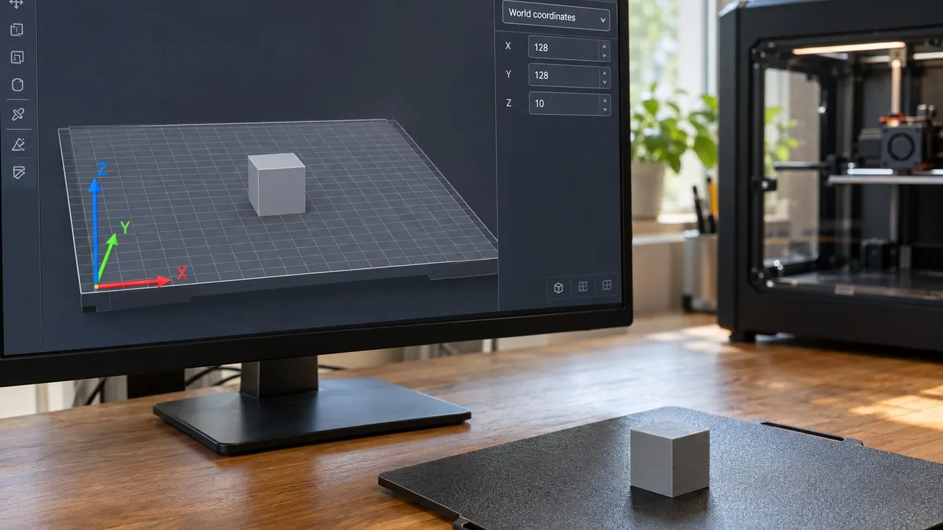
Open the Move tool in Bambu Studio and the panel starts with a dropdown set to World coordinates, with Object coordinates as the one alternative. Picking between them only makes sense once you know which way the axes point, and that is the question a Bambu Lab forum user asked in March 2024 in a thread titled "What is X Y Z?". They had guessed that Z was height and sketched their guesses for X and Y over a screenshot.
The accepted answer handed them a picture to hold on to:
When you hold the board with both hands and feed it into the printer, the right-hand direction is X+, and the direction of feeding into the printer is Y+.
Z points up, as the poster assumed, and they replied that they got it. The picture holds up against Bambu Studio's source code. The source also answers things the thread never reached: where zero sits, what the two coordinate modes actually change, and which keys give the direction away.
Two marks on the plate
The answer tells you to find two things on screen. The first is what it calls the positioning mark, on a thin strip along the front edge of the plate. The strip is a texture that changes with the plate type (for the Textured PEI Plate it is bbl_bed_pte_bottom.svg), placed by the source just in front of the Y = 0 line, and it lists the compatible filaments next to a HOT SURFACE warning. The mark the answer circled in blue sits at its right end: a square between two upward arrows, pointing toward the back of the plate, the direction you slide it in. Not every strip has it. On the X1, P1 and A1 series the Cool Plate and SuperTack strips leave it out, and so do the PEI strips on dual-nozzle machines like the H2D. The answer's screenshot used a Textured PEI Plate. If your strip has no mark, go straight to the corner arrows.
The second is a set of three arrows in the corner. In the source these are the bed's coordinate axes, colored red for X (#FF0000), green for Y (#00FF00) and blue for Z (#0000FF), all starting at the world origin, 0,0,0. Each shaft is a tenth of the largest dimension of the build volume, 25.6 mm on a 256 mm bed, with a 5 mm cone on the tip. The forum answer calls them the indicator in the lower left corner, and from a front view that corner does land at the lower left. So if the red arrow points right and the green one points away from you, the strip is the edge nearest you and you are looking at the plate the way the answer describes.
Zero is the front-left corner
Bambu's printer profiles define the bed with printable_area, and every current profile starts at the 0x0 corner:
| Printer | printable_area | printable_height | bed_exclude_area |
|---|---|---|---|
| X1 Carbon, P1S | 0x0 to 256x256 | 250 mm | 0x0 to 18x28 |
| A1, P2S | 0x0 to 256x256 | 256 mm | none |
| A1 mini | 0x0 to 180x180 | 180 mm | none |
| H2D | 0x0 to 350x320 | 325 mm | none |
That 0,0 is where the arrows start. On the X1 Carbon and P1S profiles the excluded zone sits right there too, an 18 by 28 mm rectangle beginning at the origin.
Where people usually get lost is the Position row in the Move panel, because its X and Y are not the corner of the model. They are its reference point. Going by the load logic in the source, an STL, STEP or OBJ is centered on its own bounding box when it comes in, so a model sitting in the middle of a 256 mm bed reads about 128 / 128 rather than 0 / 0. By the same arithmetic, a freshly loaded, unrotated model shows half its height in Z: 10 for a 20 mm cube. The same world coordinates explain a surprise on a second plate: according to the source, plate 2 on a 256 mm bed starts at X = 307.2 (the plate width plus a fifth), so a model sitting there shows an X well past 256. Nothing is broken.
The Size row in the Scale panel follows the same X, Y, Z order. In the first screenshot in the thread, the model is already scaled to 47.01% and still measures 1612.92 x 1878.35 x 605.95 mm, with a red error saying an object is laid over the boundary of the plate or exceeds the height limit. The answer never mentions it, but no rotation would have fit that model on a 256 mm bed.
World coordinates vs. Object coordinates
Press M for Move and the dropdown sits at the top of the panel. It arrived in version 1.10.0, first as an October 2024 beta and in the stable release that November. Back in the 1.8 releases current when the thread was posted, the Move panel only printed the words World coordinates, with no choice to make.
- World coordinates: the row is labeled Position and the values are absolute, measured along the plate's axes. Type a number and the model's reference point goes to that coordinate.
- Object coordinates: with a single object selected, the row turns into Translate(Relative) and the boxes start at zero. What you type moves the model that far along its own axes. If the model has been rotated those are not the plate's axes, and in this mode the source draws a small red, green and blue cross at the model's center, turned with the model.
The second mode is the one for nudging text or a part a few hundredths of a millimeter into a surface. The user in the assemble and merge article did exactly that, typing -0.01 into the Z box.
The choice does not stick. The source switches the panel back to World coordinates every time you open the Move tool, and again when you pick a different part. Select several whole objects, or the prime tower, and Object coordinates drops out of the list altogether.
The Rotate panel has no dropdown. It simply prints World coordinates at the top, over a Rotate (relative) row and a Rotate (absolute) row. Scale offers World and Object coordinates, plus Part coordinates once you select a single part. How the tools themselves are used, including Place on face and uniform scaling, is in the rotate and scale guide; this article only covers which axes they use.
Letting the keyboard tell you
The quickest way to settle any doubt is the arrow keys. According to the shortcut list in the source, with something selected:
| Key | Result |
|---|---|
| Up arrow | Moves the selection 10 mm toward +Y, the back |
| Down arrow | 10 mm toward -Y, the front |
| Left arrow | 10 mm toward -X |
| Right arrow | 10 mm toward +X |
| Shift + arrow | Step drops to 1 mm |
| Ctrl + arrow | Moves relative to the camera instead |
Camera views are Ctrl plus a number, Cmd on a Mac: Ctrl+0 default, Ctrl+1 top, Ctrl+2 bottom, Ctrl+3 front, Ctrl+4 rear, Ctrl+5 left, Ctrl+6 right, Ctrl+7 isometric. Top view reads like a map, +Y toward the top of the screen and +X to the right, and the default view puts the camera in front of the plate and 45 degrees up, the perspective the forum answer describes. The same list lives in the View menu, which on Windows is a submenu of the dropdown at the top left and on macOS sits in the menu bar.
Leave off the Ctrl and the digits do something else: 1-9 assign that filament slot to the selected object, which makes it easy to recolor a part when you meant to turn the camera.
Since 2.0.0 (March 2025) there is also a 3D navigation cube in the lower left corner of the 3D view, faces labeled Front, Back, Top, Bottom, Left and Right. It is on by default and toggles with Show 3D Navigator in the View menu. It is not the indicator the forum answer meant; the cube did not exist in 2024, and the answer was pointing at the arrows on the plate.
Version 2.4.0, released in November 2025, added an alignment section to the Move panel that only appears with World coordinates selected. At first it needed at least two parts or objects selected; since 2.5.0 (January 2026) it shows up for a single object too. Its tooltips spell the directions out: Align left (-X), Align right (+X), Align front (-Y), Align back (+Y), Align bottom (-Z), Align top (+Z). Front is -Y and back is +Y, exactly as the answer said.
The slicer's axes and the printer's
These coordinates carry through to the exported file. The G1 X... Y... Z... moves are written in the same printable_area system, and if you want to read them line by line, start with the G-code primer. With several plates, the source subtracts each plate's origin as it writes the G-code: a model in the middle of plate 2 that shows an X of 435 in the Move panel is written at around 128 in the file.
The hardware is another matter. A Z axis that fails while homing has nothing to do with the blue arrow in the slicer, and that problem has its own write-up in the Z homing article. The slicer's convention is the same across every current Bambu profile: 0,0 at the front-left corner, X+ to the right, Y+ into the machine, Z+ up.